
John "Sean" Greenslade
Panoramas Part 1 - Theory
Panoramic photography is, broadly speaking, the process of producing photographs that have a much wider field of view that an average photo. My technique for producing panoramas is called photo stitching. Photo stitching is the process of taking multiple images of the same scene and combining them into one larger photo. This can accomplish several things: higher resolution images, wider angle images, or both. When taken to the extreme, the field of view of an image can be increased to cover the entire viewable area. This is called a spherical panorama, since it results in an image that can be mapped to the inside of a sphere. Similar to how a planetarium shows you the inside of half a sphere, a spherical pano viewer shows you the inside of a full sphere.
But what does a spherical panorama look like? Rather weird, as it turns out, unless you're viewing it in a proper pano viewer. There are lots of different ways of representing and storing panoramic photos, but the simplest is the equirectangular projection. A full spherical panorama rendered as an equirectangular projection looks like this:
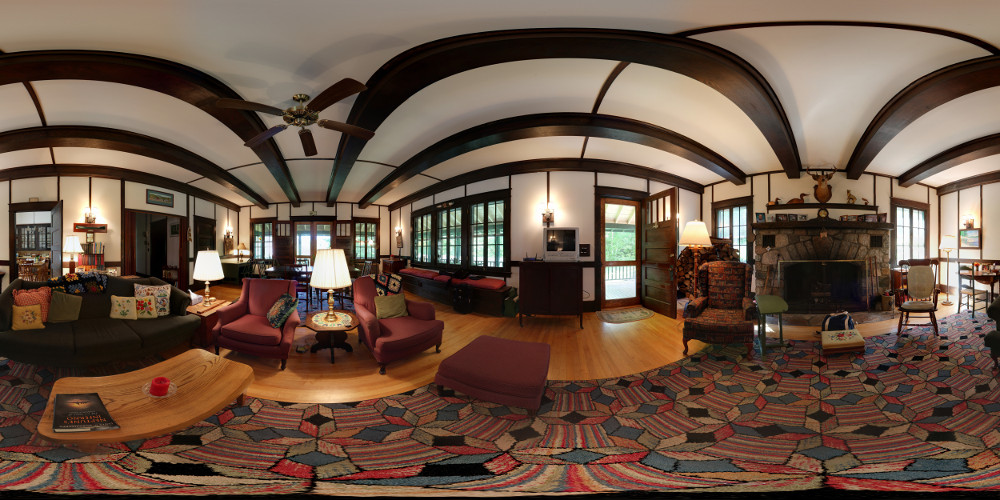
In the world of maps, this would be similar to a Mercator projection. It works by taking the sphere and stretching the zenith (north pole) and nadir (south pole) out in such a way that the sphere becomes a cylinder, then unwrapping the cylinder to a flat rectangle. Equirectangular images are always twice as wide as they are tall, since their width represents the equitorial circumference of the sphere while their height represents one trip from north to south pole (half a circumference). (Note that true Mercator projections have a non-linear vertical scale, whereas the equirectangular projection does not.)
This projection leaves much to be desired, however. The poles are extremely distorted, since they stretch a single point out to the same width as the equator. Thus, another common projection format is the cube map, or cubic projection. The same panorama rendered as a cube map is shown below:
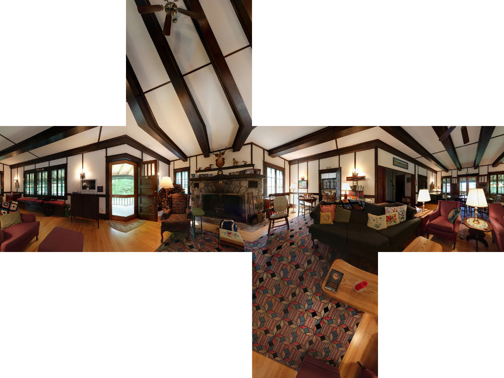
This projection interprets the scene as a cube, projecting the sphere onto 6 square tiles: front, back, left, right, up, down. This projection maintains straight lines within each tile, and when the tiles are formed back into a cube, the seams do not introduce any distortions. The seam lines are visible in the above image due to the fact that it has been unfolded and flattened.
The projection these tiles use is similar to the projection that normal cameras use. Standard camera lenses produce what is called a rectilinear projection. The rectilinear projection maintains straight lines in all directions. Thus, rectilinear projections begin to look strange at greater than 90-degree field of views, and cannot represent any field of view greater than 180 degrees. Field of view is simply how wide of an angle a given image / projection covers. A standard zoom lens will decrease in FOV as it zooms in tighter. The following image is rendered rectilinearly with an FOV of 170 (extremely close to the mathematical limit):
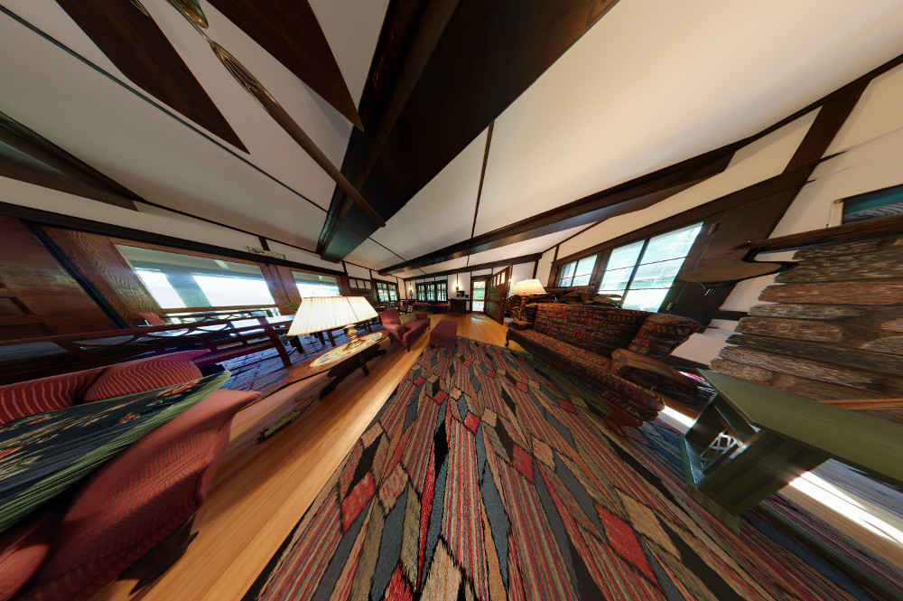
Notice that despite the extreme distortion of the image, all straight lines in the scene are still stright. Most of the detail in the center is lost, however, which is why you'll typically find wide-angle lenses use fisheye projection instead of rectilinear. It's also a lot easier and cheaper to produce fisheye lens optics than wide rectilinear lens optics. But we won't be dealing with fisheye projections in any of these panoramas, since I don't happen to own any good fisheye lenses (good ones are expensive).
That's enough about projections for now. Just remember that we're dealing with a spherical pano. The basic process of constructing a full spherical pano is as follows: First, images of a scene must be captured. Second, the images must be aligned, masked, cropped, and optionally pre-processed. Third, the images must be re-projected and blended. Simple enough, right? Let's dig a little deeper into the details.
The first and most important detail to understand is that despite what I said earlier, cameras do not produce a rectilinear image. Due to the fact that real lenses are optically imperfect, small distortions are introduced by the camera. Here is a picture of a sleepy puppy, first straight from the camera unaltered, and then with distortion correction applied:
These errors may seem small, but they add up over the course of an entire pano. Luckily, we can mathematically model the distortions and apply their inverse to the images in order to undo them. Also, since the distortions are constant given a specific camera and lens, once we find the distortion parameters of our system, we can apply them in reverse to all our images and end up with nearly perfectly rectilinear images. Yay!
But how do we model those distortions? Math is hard, after all, and we don't want to do any math. We just want pretty pictures. Well enter our best friend and closest ally, Hugin:
![]()
Hugin is an open-source (yay!) program that is totally awesome. Hugin provides a fancy UI for manipulating images, and its friends CPFind, Nona, Enblend, Enfuse, and others provide the heavy-lifting backend to literally bend our images to our will. Hugin does its best to help us out in a lot of different ways. In particular, Hugin provides a control-point-based system for automatically(ish) aligning images and determining distortion parameters. Basically, all we have to do is tell Hugin which points in overlapping regions are the same points in the scene. And sometimes we don't even have to do that! CPFind can do image analysis and detect likely overlap points using more fancy math. Nifty!
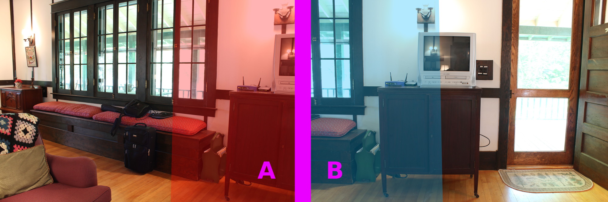
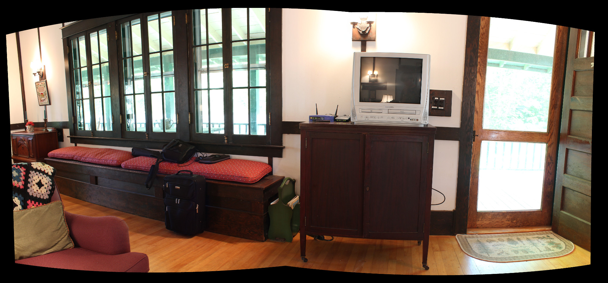
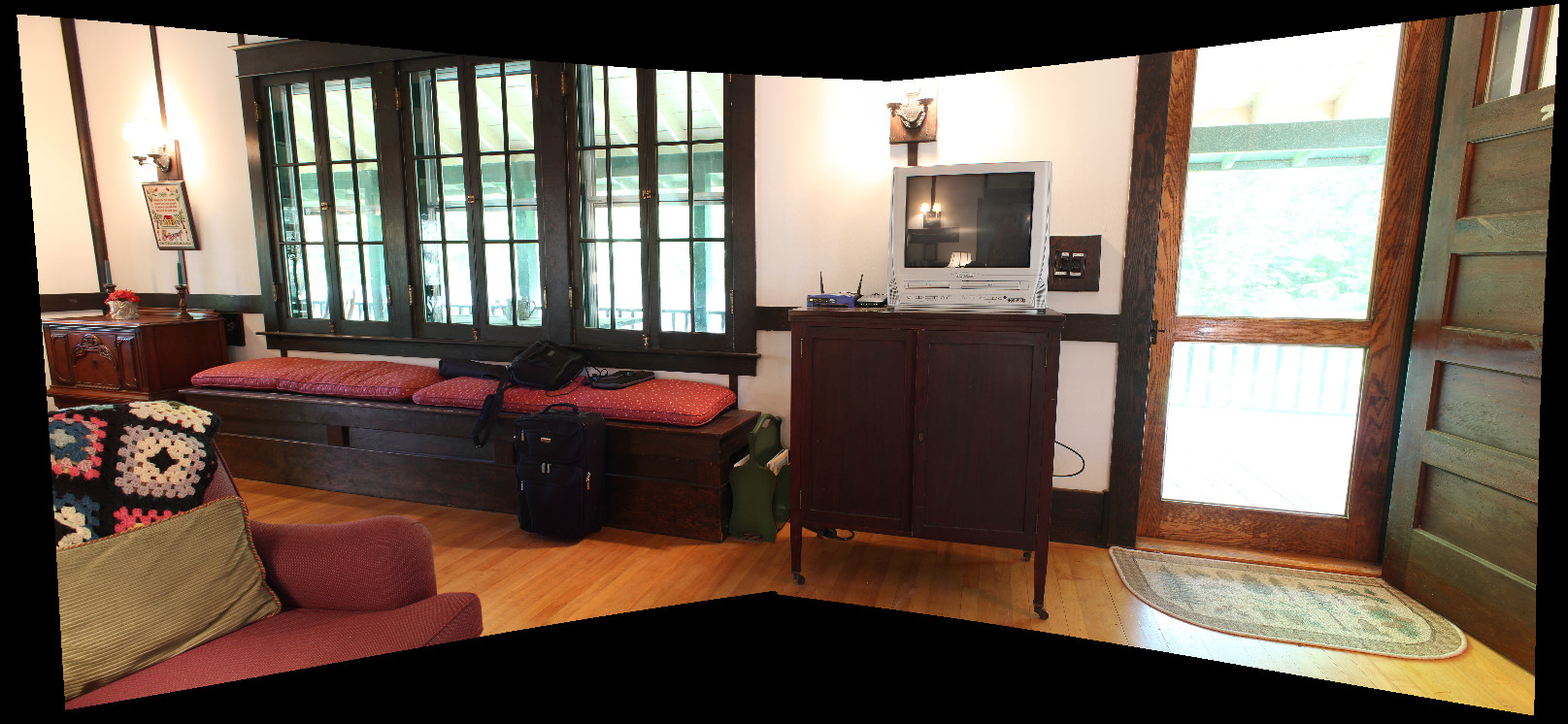
But hold on a second. What did I mean by overlap regions? What exactly am I doing with my camera when I'm shooting a pano? Well as I mentioned before, the final stage is blending multiple images together into one. Since our goal is to have a full sphere of photos, we need to shoot images that cover every possible angle. But to blend these images together nicely, we need to overlap them. For demonstration, we'll use the following two images:
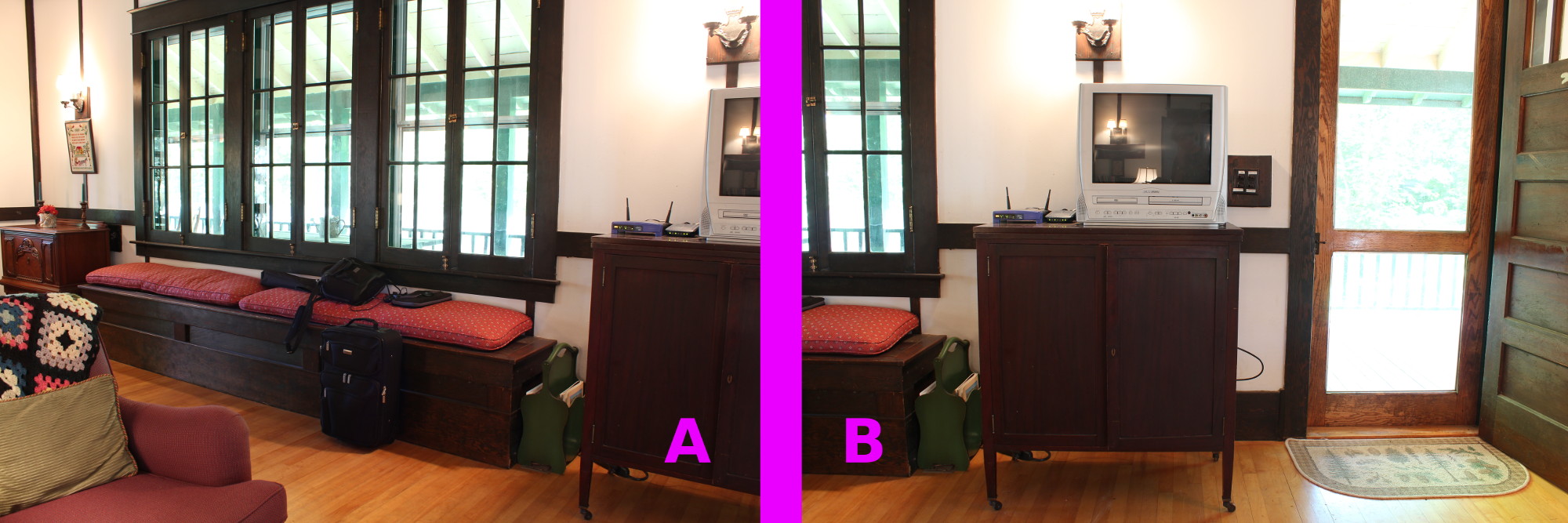
Notice that the right area of image A (the TV stand and bench) and the left area of image B are the same. This is the overlap region, which we've highlighted:
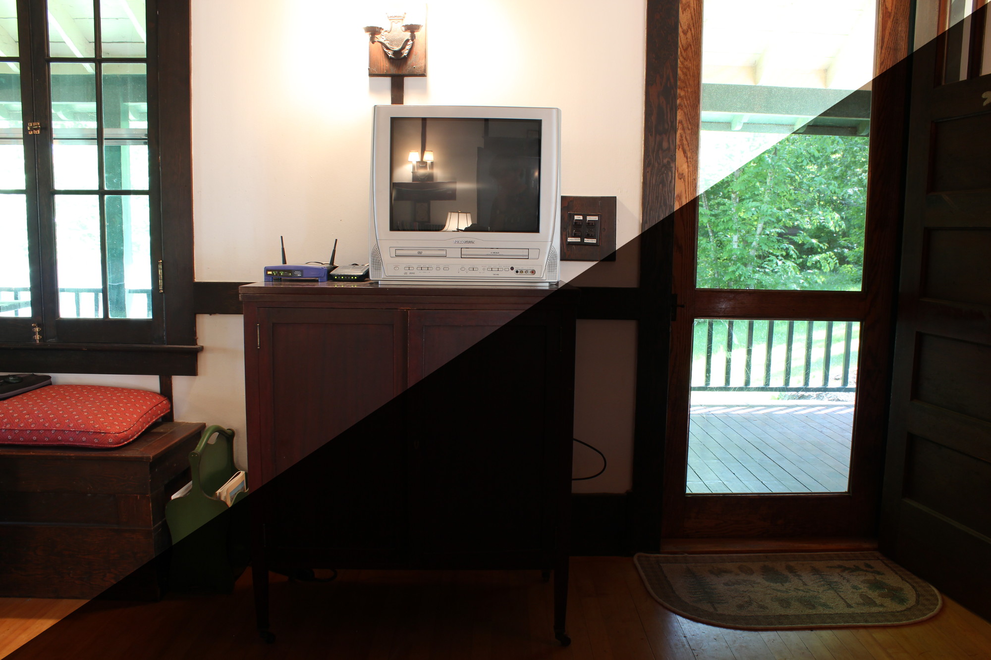
But what happens if we try to line these two images up by simple overlap?
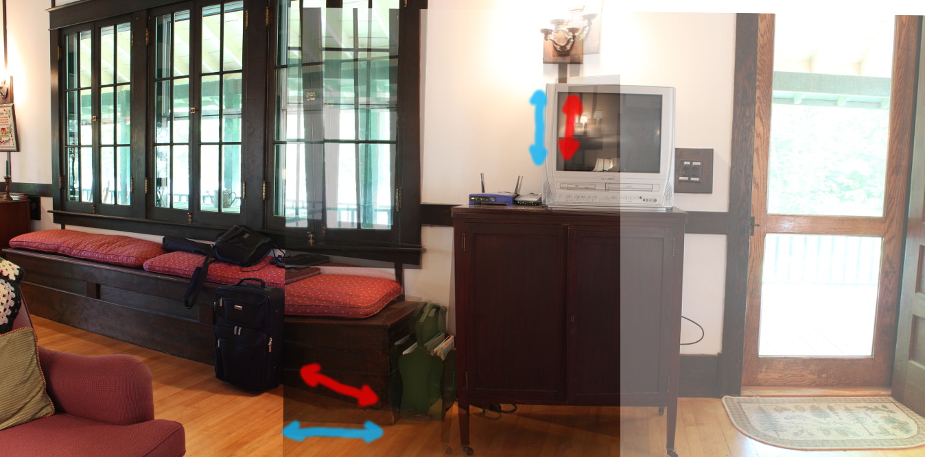
No dice. This is impossible since we're not accounting for the projections of the images. Notice that in two different areas of the image, the rotation angle is different. There is no way I can move and spin these images and make all areas of them align.
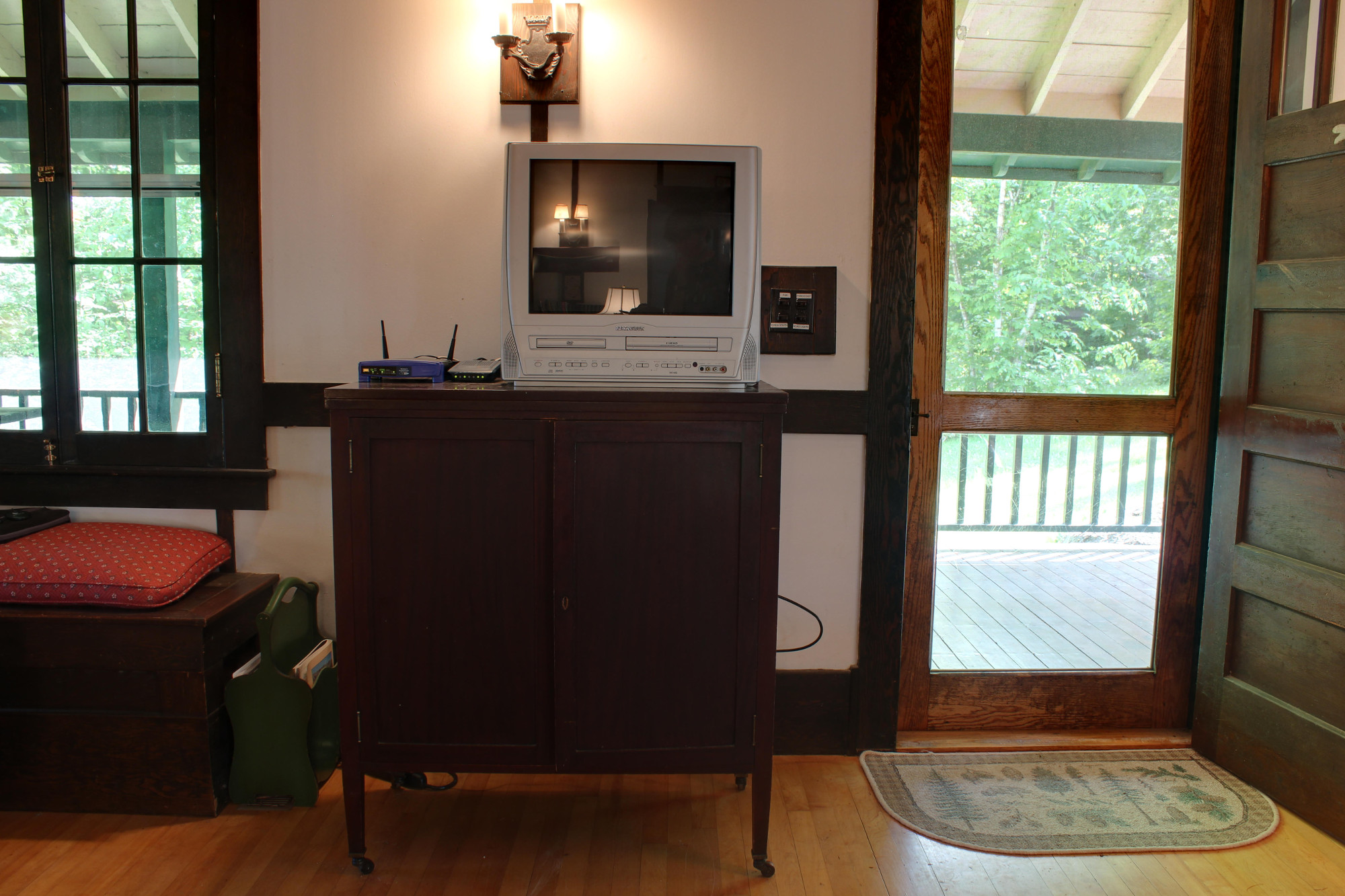
Hugin, on the other hand, treats these images like projected portions of a sphere. By warping the images to partial spheres, alignment now becomes possible. Here are the two images after being warped:
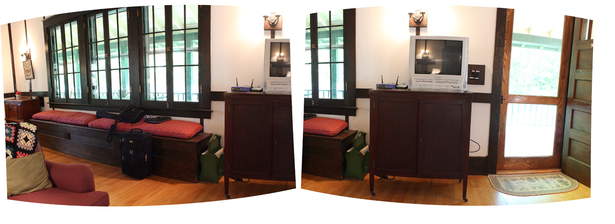
The images can then be overlapped perfectly:
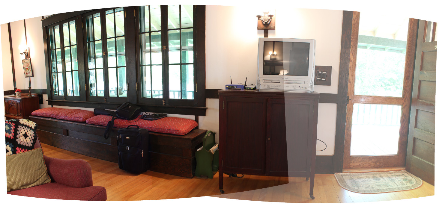
And finally, the images are blended:
The image can also be un-warped back to rectilinear coordinates as seen in this second render:
But remember, we can only render this pano in rectilinear form becuase it is a partial pano. That 180 degree limit still holds. Since our goal is a full 360x180 degree panorama, we'll need to render in a format that can handle the full sphere. I typically use equirectangular since it's easier than trying to wrangle 6 cube faces at once. Hugin supports many different projection types, and switching between them is fairly easy.
Hugin does a lot more than just the projection warping. In addition to the positional lens distortion estimation, it can also estimate and correct for errors in color / white balance, exposure, and vignetting. Each of these is a potential variation in the images that makes blending more difficult. One of these that can be particularly problimatic is exposure. Cameras are unable to see the same range of brightness values that humans can (the difference between the brightest and darkest point in a given view is called dynamic range. To compensate for this limited dynamic range, Hugin supports a variety of high dynamic range processes. HDR allows us to capture a scene that has both very bright and very dark regions visible. Since the camera cannot expose for both simultaneously given its 8-bit dynamic range (slight lie here, more on this later), we can take multiple shots of the same image at different exposure values. Here is an example of two images shot in the same place at two different exposure targets:
Notice that the windows are well exposed in the lower half, but the inside is too dark. Conversely, the windows are too bright in the upper half but the inside is well exposed. After fusing these images, the result is an image that uses the most well-exposed areas of each source image to make a more evenly-exposed final image:
A program called Enfuse is used for this task. It applies several heuristics to determine which areas of each image are the "best" and merges them accordingly. This is a different process from the standard tone mapping method of a true HDR workflow. It still ends up being a low dynamic range output (8 bits per color channel), however the entire photo is now properly exposed in a way that the camera could not capture in a single frame.
So now we know the basics of panos. Next step: shooting our pictures.